
After having covered the prototype details elsewhere on this website, this piece looks at modelling them and specifically upgrading the body from the Airfix/Dapol kit. Hopefully this will be of interest beyond those building the Rumney Models kits. Those wanting a blow by blow account of building the underframe on which they sit can consult the instructions.
The venerable Airfix Presflo wagon kit was released way back in 1961. Goodness knows how many have been sold over the years either by Airfix or Dapol after they took over the kit’s manufacture. It seems inconceivable now that you could buy them on the high street through shops such as W H Smith but, once upon a time, you could. Nowadays you’d be lucky to find one in a model shop. This once wide availability is good news though for those wishing to model a Presflo as there are plenty of unstarted kits on the second hand market and the most recent Dapol release is best avoided. For some inexplicable reason, they put a big gouge down the sides of the hopper rendering it near useless. The kits to avoid are those moulded in dark grey plastic. It’s a good job I only ordered one of these… Earlier Dapol production, moulded in a light grey plastic, are fine and all my four are from this vintage. I’ve been told that if you can get an Airfix one in good nick the quality of the mouldings are better.
We should not entirely discount the Bachmann model. My original intention had been to model two BR Presflos with the Dapol kit and two APCM with Bachmann bodies that I’d had for ages. As always seems to be the case though, they are the same but different. This is not to denigrate the Bachmann model too much as both have their issues but having decided that I might want to run all four together and detailed two Dapol kits, the two types looked too different next to each other to continue with the Bachmann version. It is also much easier to detail and modify the Airfix/Dapol kit, which is what I will deal with here.
I don’t know where Airfix got their information from but, the kit they produced seems to be a bit of a mix of types. It was obviously intended to be one of the first batch of APCM Presflos and the arrangement of the pressure gauge, which was different to that on BR wagons, and the representation of the discharge pipe would suggest this. The sides, however, have a rounded change of angle which was not a feature of that first batch of APCM Presflos built by Butterley which had a sharp change of angle. It turns out it is pretty good for a Met Cam built APCM Presflo but curiously they hadn’t been built when the kit was released! This means that, as well as making it look a bit better, there are elements that need to be changed if you want to do a BR built Presflo with it.
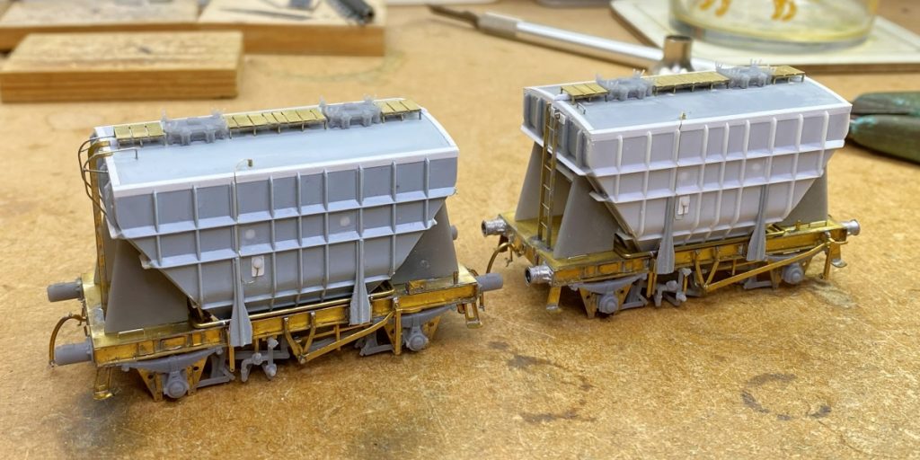
Firstly, a little prep work. The kit comes with holes in the sides to locate spigots for the side stanchions and trader’s boards and also holes in the roof for the plastic walkways. The holes you don’t want need to be filled in. That will mean the roof and, if you’re modelling a BR or Tunnel Cement wagon, the holes in the tops of the sides. Further, if you’re modelling one of the Shildon built Presflos soon after they were built, you’ll have to fill the holes for the stanchion locating holes as well. I used Evergreen 1/16” plastic rod (Item No. 222) with a tapered reamer to open out the holes. Do this slowly and keep checking so the rod is a nice tight fit. Cut the ends nice and square and try to get them as flush as possible without having a recess. The roof is easy enough to get smooth, but the sides are tricky due to the ribs sticking out and the softness of the plastic. I used a sharp chisel blade to take most of it off, but it is easy to dig into the plastic body. I resorted to strips of emery paper wrapped over a length of brass strip that could fit in the space to finish them. It took a while, and a couple of attempts, but a smooth surface can be had with no sign of the holes that were there.
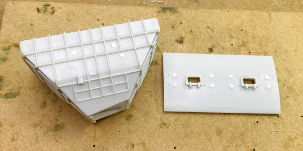
With the holes in the roof filled, the drilling jig in the kit was used to drill new holes for the replacement walkways and then the bottom of the manholes removed and filled smooth. It’s important to do it in this order as the plastic manholes are used to locate the jig.
As mentioned above, the pressure gauge and its mounting are in the wrong place for the BR version. If you need to, carefully carve it off. I made a replacement using a piece of 0.005” plasticard cut to 4mm x 2.33mm for the backing plate. Once this had been welded in place and gone hard a 1.5mm hole was drilled for at the gauge centre. This was carefully opened out so that a short length of 1/16” plastic rod could be fitted for the gauge itself. A small 0.3mm hole was drilled at an angle just below the gauge to allow for a wire for the pipe.
If you’re modelling an APCM wagon, there was a small metal plate fitted just to the right of the centreline about level with the gauge glass on the angled part of the hopper. The face of this is vertical and works out at approximately 1.33mm x 2.5mm but is set against the angled part of the hopper so some shaping is going to be required. I started with a piece of 0.75mm x 1.5mm strip cut to 2.5mm long. I then thinned the 1.5mm wide part a little to get a bit closer to 1.33mm and shaped it to sit against the angled part of the hopper, so the front face was just about vertical.
There is no representation of the angles that joined the sides and end to the roof. The Bachmann model has it and looks much better for it. This can be added to the roof section, but you will need to carefully file back the stanchions on the sides and ends to get the slightly bigger roof to fit. I found it easiest to modify the roof at this point but leave the sides and ends until the body is assembled. The tops of the stanchions are quite vulnerable, and this work is best left as late as possible. Using 0.005” plasticard, I cut a strip 3.5mm wide and glue to the ends of the roof. Once it has hardened, it can be carved to shape with the top flush to the roof profile. Cut strips of 0.005” plasticard to ~1.3mm wide and use these for the sides of the roof and the top part of the angles. Do the sides first and make them the full length of the roof. The ends can then be fitted between the sides.
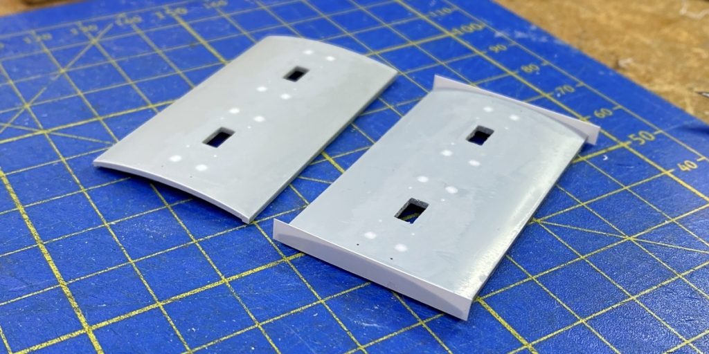
With the prep done attention can turn to assembling the body.
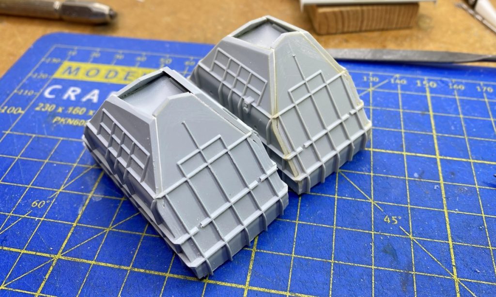
Whenever I assemble a plastic kit, I always start by tacking it together with plastic cement. I have a small bottle of Revel Contacta Professional on my workbench for this purpose. If used sparingly, it is a simple matter to get the thing apart again if you’ve ended up with bits slightly misaligned or if something isn’t quite square. Only when I’m completely happy do I reach for the Butanone and lock it together permanently. This approach proved useful on a couple of occasions whilst building my Presflo bodies, not least when assembling the basic sides and ends. If I had reached for the plastic weld from the start a couple of the bodies would have been scrap as there is no way I would have got them apart without damaging the parts.
The shape of the hopper doesn’t help, four parts and 8 planes doesn’t make life easy for the tool maker, but I found that if you assembled the vertical parts of the hopper so that they are as square as possible then there are slight gaps in bottom angled part. I found this out by trying to assemble them so there were no gaps and the result wasn’t very true. Not a problem to fill the gaps with pieces of plasticard and filler but it was very handy to be able to rectify things when they weren’t right.
With the four sides of the body done, thought needs to be turned to how you weight it. The obvious place for it to go is in the hopper. The kit includes a floor that was fitted and then plastic strip used to create a recess into which a piece of lead sheet can be fitted. I do get a bit paranoid about bits of ballast coming loose and rattling around inside a closed space so I take care to try and trap it in place somehow. I also prime the lead before fitting. I have had instances of lead glued in place oxidizing and expanding. The lead was glued with epoxy which shouldn’t cause any issues, but I think the problem was fumes from a glued wooden box and shelf brackets inside a box which were done with PVA. Anyway, I now take no chances. My motto is, do a job so you don’t have to do it again, even if it takes longer. It would be helpful if I could tell you how much lead I added and I thought I had made a note, but I can’t find it. I aim for 45g for everything but the wheels and spring carriers.
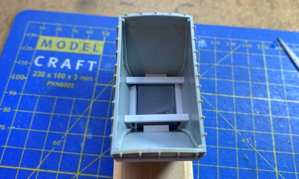
With the ballast fitted, the roof can now go on. Carefully take back the stanchion tops on the sides and ends with a fine file. Go slowly and keep checking the fit until the roof fits in place. Once happy, glue in place. Any gaps can be filled in. I used white milliput.
Next attention turned to the ends. The Presflo had horizontal angled metal ribs fitted around the hopper to strengthen the platework. These were all the same length on the sides and ends on the prototype and, I think, on the two Shildon lots when built. They also lacked side stanchions. This arrangement was found to be insufficient, so side stanchions were fitted and additional ‘fin’ pieces were added on the ends to strengthen the ribs, but they weren’t all the same length. On the Shildon built Presflos they gained long fins on all three rows of horizontal ribs. The lot 3029 wagons built by Met Cam seemed to have them only on the top row when built but some wagons gained them on all three later in life. After this, things seemed to settle down with long ‘fins’ on the top two rows only and shorter ones on the bottom. As it comes the Airfix/Dapol kit resembles the prototype with no ‘fins’ at all on the end ribs, probably to make the tooling easier. I added them to mine using lengths of 0.25mm strip, either 1mm wide for the long ‘fins’ (Evergreen No. 102) or 0.5mm wide for the short ‘fins’ (Evergreen No. 100). As with the body I tacked them in place with cement and then welded them in place when I was happy with their positioning. The ends were trimmed either straight or angled depending on the porotype using a sharp scalpel blade once things had hardened. It’s worth putting in this effort with the ends as the ribs are really a bit undersized and the ‘fins’ give everything a bit more presence.
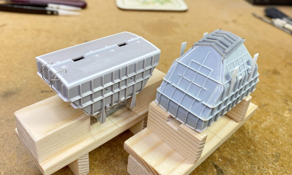
There also seems to be a horizontal rib missing from the ends. Bachmann also missed this as did Ellis Clark with their recent 7mm model. This was added using short lengths of 0.75mm x 0.25mm strip (Evergreen No. 101). On the Airfix end there are four horizontal ribs on the end, three full width and a shorter one at the bottom. The missing rib goes a bit above halfway between the two lower full width ribs. Be aware that it only extends between the end stanchions and not beyond.
A test fit was made with the body, underframe and end stanchions and the ribs/fins on the ends tweaked with a scalpel if the end stanchions didn’t quite fit.
I used the Dapol side stanchions on my four, cutting them off the underframe and filing any excess from the bracket off. They were glued in place and then checked on the underframe, tweaking the backs of the stanchions if necessary to ensure a vertical fit. The 3D printed version used in the kits hadn’t been done when I built the bodies, but I would use that now to save time. If I was really picky the early builds with a single vacuum cylinder had a different patten of wedged shapes strengthener on the side stanchions once they were fitted. The Shildon builds didn’t have any side stanchions when built and so the vertical ribs would need adding in the gap if you were modelling one of these soon after building. The lot 3029 wagons built by Met Cam had plain T-shaped side stanchions initially with strengtheners added later.
On the roof there is a strengthening rib that runs along the apex of the curve. On the prototype this extends from the middle vertical end rib. I added this using 1mm x 0.5mm strip (Evergreen No. 122) leaving gaps for the manholes. I shaped the outer ends to match the angle at the top of the middle vertical end rib and trimmed around the manholes with a scalpel when I fitted the 3D prints.
There were two arrangements of pipe for the pressure gauge. On early BR builds this was a simple affair with the pipe looping around from the bottom of the gauge to run along the inside of the stanchion immediately to the left. At the top this looped over and entered the roof of the hopper. I used, I think, 38 SWG soft brass wire for the pipe and a short length of 0.5mm x 0.3mm tube (Albion Alloys MBT05) inserted into the hopper on the roof into which the wire was fed.
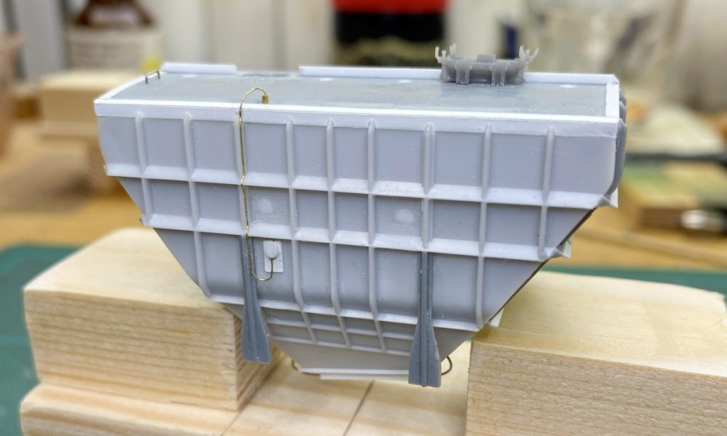
The later arrangement, which all the early ones seemed to be converted to in the 1960s, featured a more substantial pipe coming out of the top of the hopper and running down the centreline of the wagon. There was a join in this pipe just above the top of the solebar into which the small pipe from the pressure gauge fed. For the main pipe I used a print included in the kit with 38SWG soft brass wire being feeding into it from the gauge.
The two Shildon lots had a different ladder arrangement to everything else. This early type of ladder was a fairly simple affair and was fixed to a plate at the end of the hopper which went between two of the vertical ribs. I made the plate from 0.25mm thick plasticard cut into a 2mm wide strip and glued to the ribs. There was a short handrail (~3.5mm long) on the top of the hopper just in from the end. I added this from 0.3mm wire inserted into holes drilled into the roof with the inner end roughly lining up with the outer rail of the ladder.
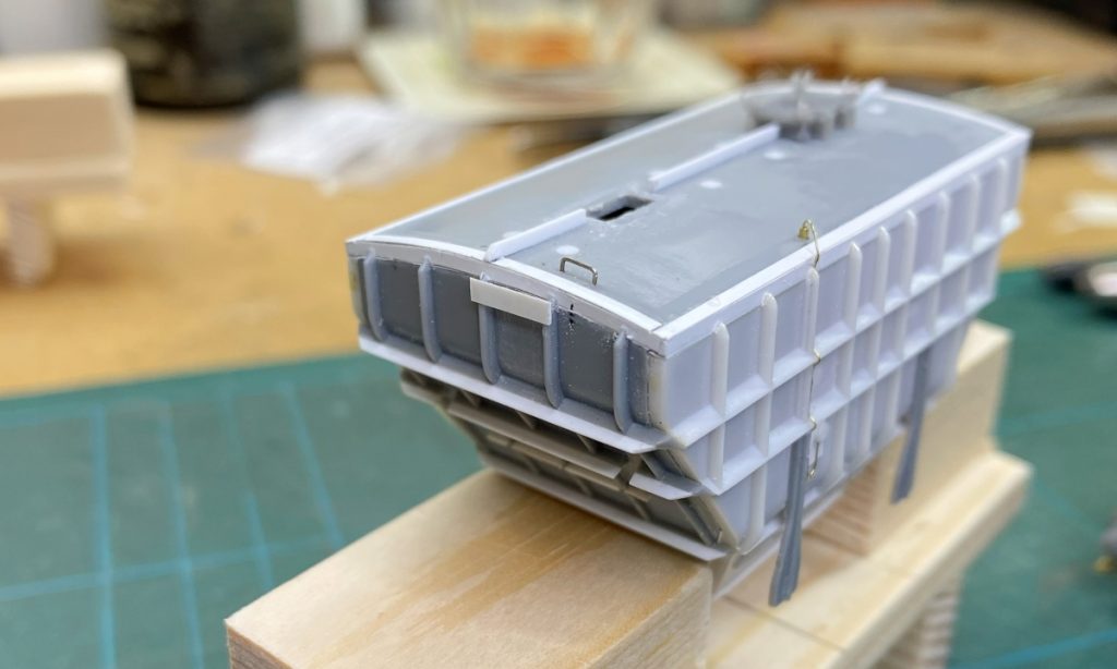
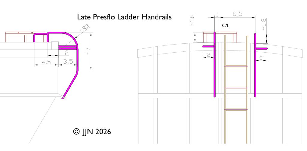
Later ladders and handrails were more involved. The ladder curved over at the top to be welded to the roof of the hopper. Either side were handrails which were fixed to the top of the hopper and, aside from the curved changes in direction, followed the shape of the hopper before angling in and fixing to the top strengthening ‘fin’ on the upper horizontal end rib. The handrail along the wagon centreline was shorter at the top than the other as the walkways would have got in the way it being the same length as the other. Off both handrails there were stays that fixed to the curved angle that joined the end and roof. The ladder on the models came from the kit and the handrails were made from 0.3mm wire inserted into holes drilled in the body. I made a rough sketch to help with forming them and soldered the stays to the handrails in situ.
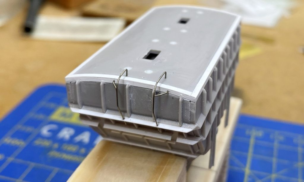
The rest of the detailing used parts from the kit.
The Airfix/Dapol kit comes with no bottom for the hopper. It transpires that this is different for the BR builds and those built for APCM and Tunnel Cement. The correct version was fitted to hopper for each type. The private owner version has pipes that come out of bars that ran along each side of the hopper bottom and then disappeared into the hopper. These were made from 0.3mm wire and inserted into holes drilled in the hopper and hopper bottom.
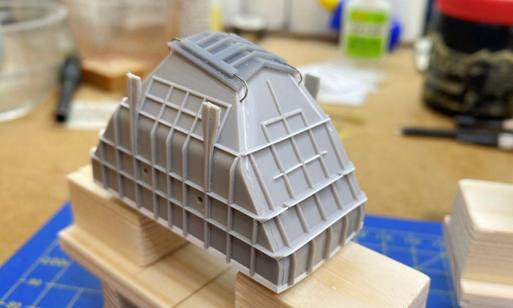
3D printed end stanchions were one of the first things created beyond the etches. The Airfix/Dapol kit has a very thick floor to which the end stanchions are attached. This would have need a fair bit of work to sort out and then there’s the question of the detailing at the vacuum cylinder end, with brackets for the cylinders and holes for the vacuum release cord and the rod from the changeover levers. Given this was all different between the wagons with early brakegear and one vacuum cylinder and those with late brakegear and two cylinders, it was easier to make new printed end stanchions with correct detail for each type. The Bachmann model has two lugs on the bottom of each end stanchion which locate into the underframe. This feature was useful and so was copied for the new ones.
Manholes were added into the slots in the top of the hopper. The strengthening rib that runs along the top of the roof was trimmed at this point so that they finished neatly against the manholes. The manholes are arranged so the hinges are on the same side as the discharge pipes except on BR built wagons to lot 3175 where they faced the other way. There’s always one…
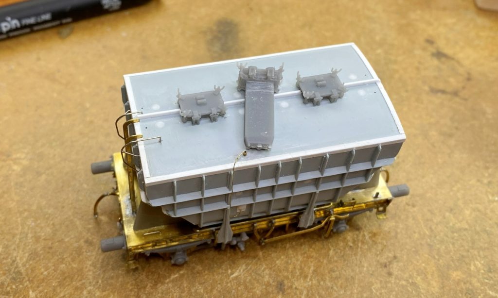
Walkways were the last thing to do. The originals are more than a bit clunky so etched ones replaced them. They need the middle supports filing down along the centreline to clear the strengthening rib. They fit into holes drilled earlier in the roof. I fitted mine after I had primed the body and the underside of the walkways themselves. I figured it was going to be tricky to paint the underside with them already in place and I was bound to miss a bit and be looking at unpainted brass at some point. The tops were primed after fitting. They could perhaps have been blackened before fitting instead.
There was a lot of work to get the hopper body looking the part and at times I began to appreciate the merits of the Bachmann one. It’s not really difficult work though and nice to be dealing with a medium that allows you to do it. Usually, I am amongst the first to decry RTR manufacturers for duplicating decent kits or other RTR models unless there is something really wrong with it. In the case of the Presflos there is probably still scope for a definitive version though I think they’ll probably struggle to cope with all the variations as Ellis Clark seems to have done with their 7mm model.
Justin Newitt – September 2026